Description
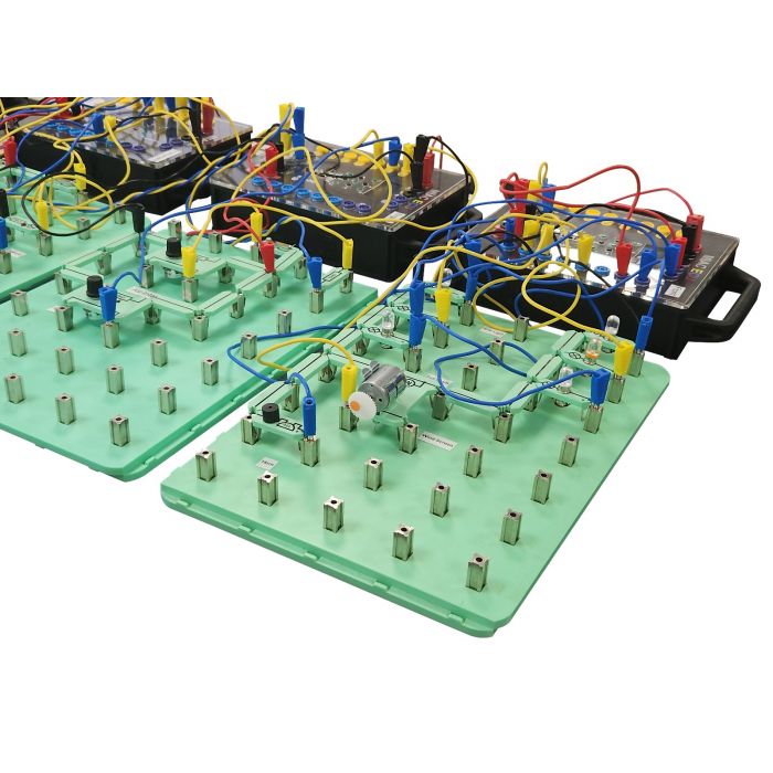
This kit consists of 6 MIAC NXT educational Electronic Control Units and accompanying Locktronics boards which
mimic the electrical system in a vehicle.
The system includes 3 CAN bus networks at different speeds: CAN
convenience bus, CAN drive train bus, CAN OBDII bus and a LIN bus for the instrument cluster. One MIAC NXT
performs the function of a Gateway ECU which provides communication between the system and OBDII scan
tools.
The 6 Locktronic / MIAC nodes are:
A – Body and control front
B – Engine control
C – Instrument control
D – Powertrain control
E – Body control – rear
F – Gateway and master
The CAN and LIN bus system can be enhanced through the addition of real automotive sensors and actuators
that are added to the system.
Accompanying free curriculum is provided for Level 3 students (CAN and LIN BUS fundamentals) and level 4/5
students (CAN bus: Under the hood). The system makes use of the J1939 open CAN bus standard and the J1979
OBDII standard so that it is compatible with all third party scan tools. A PC based diagnostic program provides
a graphical display of the functionality of the system and allows students to see the CAN/LIN/OBDII messages
on the buses.
The CAN and LIN bus system is fully supported by Flowcode programming software with accompanying J1939
and J1979 software libraries.
Learning Objectives:
- CAN and LIN bus wiring
- ECU function
- Network topology
- CAN and LIN bus
- Using scan tools
- Debugging CAN bus systems with a multimeter
- Circuit design for fault detection
- PC based diagnostics
- Sensors and actuators in CAN andLIN bus systems
- CAN bus message encoding
- LIN bus message encoding
- ECU and vehicle circuit function
- Gateway function: CAN to LIN, LIN to CAN
- Start up routines
- J1939 CAN bus protocol
- OBDII functions


