English | Français

2020 Skills Sheridan Competition

Sheridan College (Davis Campus) conducted their 3rd annual Skills Competition on March 4th, 2020, a day dedicated to recognize and celebrate the accomplishments of the students from various programs within the Faculty of Applied Science and Technology. Previously, professors selected their top students to compete in the Skills Ontario competition but with Sheridan’s new Skills Trade Centre, a more engaging way to select the students was brought forward.

Participants choose one stream and put their skill and knowledge to the test while engaging in a friendly competition with their peers. Some of the various streams included electrical engineering, information technology, precision machining, computer engineering, media management, web design, and welding.


AYVA was proud to be a sponsor for this years’ event. It was an honour to be able to witness the extraordinary projects presented by the students.

At the end the competitions, students and sponsors were gathered together for the presentation of the awards.

First, second and third place medals (which are made by the skills trade facility!) are awarded to the students.

Congratulations to all the winners and participants in this year’s competition!

PASCO Day of Physics – July 24, 2020

Session 1

Session 2

Session 3

Session 4

Session 5: Cool Physics Demos

  • Coupled Oscillators Smart Cart (FFT) & Friction Block+PAScar
  • Inertia Wands
  • Atmospheric pressure Demos
  • Polarizer Demo / Color Mixer / Color Mixer Accessory
  • Genecon Hand Crank Generator Coil & cow magnet on a spring
  • Eddy Currents – magnetic braking
  • Mirror pendulum demo

SPARKVUE – A resource for planning lessons during the pandemic!

With SPARKvue it is possible for teachers to collect data and steam the data to students in real time via a student device also running SPARKvue. This is possible if each device has SPARKvue loaded on it and is connected to WiFi – even if the devices are located many kms apart. So a teacher could schedule a zoom session with his/her students. Students could use a computer for this activity. The teacher could then carry out an activity on another device loaded with SPARKvue and stream this to students who would have a second device such as a tablet, chromebook or smart phone to receive the data. After using the zoom platform for some preliminary discussion the teacher could then turn control of the data over to each individual student and this student could then use all of the tools available to him/her in SPARKvue to carry out the analysis.

Has it been difficult for you to plan lessons for your students that would result in meaningful learning as they tackled them at home?

SPARKvue data collection software can be a great help here for several reasons:

  •  SPARKvue will run on a great variety of devices including smart phones, tablets, chromebooks, and computers. It is free for all of these devices except for computers, for which a license must be purchased.
  • The appearance and function of SPARKvue software is virtually identical ascross platforms.
    • An activity planned and carried out and saved on one device such as a tablet can be opened in another device such as a chromebook.
    • All of Pasco’s sensors can be used with any of these devices

  • Unlike the software of some of our competitors, it is possible to generate a number of pages in SPARKvue (actually there is no limit). This makes it possible to use a number of the displays available in SPARKvue such as a digital picture, a video clip, a graph, a table, a meter, a digital display, an assessment, a text box, and blockly coding.
  • A teacher could design and carry out an activity where most of the analysis is left for the student to complete. For example the sequence of pages could look as follows:
    • The opening page is a title page and gives a brief description of the task to be completed
    • Page 2 shows a digital photograph of the setup to be used
    • Page 3 contains a short video clip in which the teacher gives a brief explanation or where a specific technique is demonstrated – eg how to connect a pressure sensor to a syringe (for a Boyle’s Law activity).
    • Page 4 is a text box which informs students that a data run has been collected by the teacher and the following pages will instruct them how to analyze the results. For example on page 5 the page is split into two parts with the larger part on the left. Students are asked to generate a graph of the data. On the right side there are a number of questions which students must answer by analyzing the graph. This means that the students will have to know how to use the analysis tools found as part of the graph display.
    • On page 6 students could find another split page. Suppose a motion sensor was used to collect data. On the left side students could be asked to plot a graph of kinetic energy vs time. This means they would have to know how to use the calculator in SPARKvue. On the right side of the page there could be a number of questions relating to this graph.
  • SPARKvue can collect data from more than one sensor at a time. For example, an activity could be carried out in which the pH and temperature of a sample of orange juice is measured when AlkaSeltzer is added. Students could be asked to generate a graph showing both the temperature and pH of the juice as the reaction proceeds and then be asked a series of questions on this reaction.
    • As can be seen from the examples above SPARKvue can be used to carry out extensive analysis of collected data.

PASCO Wins Three “Best of Show” Awards from NSTA and Catapult-X

Wireless Smart Cart, Wireless Spectrometer, and Wireless Weather Sensor


We are pleased to announce that PASCO has been awarded three “Best of Show” awards! More than two thousand science and STEM educators participated in the first Science Educators’ Best of Show™ Awards by casting their votes for products that they felt impacted science learning. We are honored to have our products recognized in a competition designed by science educators for science educators. You can check out the winners below!

Category: Best New Technology Innovation for STEM
Winner: PASCO’s Wireless Smart Cart and Accessories
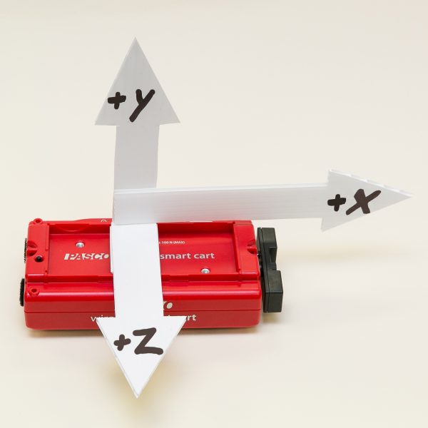
When physics educators combine the PASCO Wireless Smart Cart with the available accessories, they have a complete platform for demonstrating some of the toughest topics in mechanics. The Smart Cart’s ease of use and extensive capabilities allow students to perform their mechanics labs to a high degree of accuracy and repeatability. With sensors for position, velocity, acceleration, force, and rotation, the Wireless Smart Cart relays live data to help students test their understanding of mechanics in real time.

The wireless nature of the PASCO Wireless Smart Cart and Accessories is a definite improvement [over traditional systems]. The removal of wires needed to connect to an external interface makes data more accurate and opens up opportunity for more innovative experimentation. The accessories for the carts also are very innovative and extend the scope of investigation.

— Science Educators’ Best of Show Judge

Category: Best Tried & True Technology Teaching and Learning: Chemistry
Winner: The Wireless Spectrometer and Spectrometry software
With measurements for emission spectra, intensity, absorbance, transmittance, and fluorescence, the Wireless Spectrometer is surely more powerful than its size suggests. Its visual, user-centered design makes it easy for educators and leaners of all levels to integrate spectrometry into their learning. The key is PASCO’s Spectrometry software, which allows students to quickly generate standard curves, make comparisons, and analyze their results using its visual absorbance display. When combined, the Wireless Spectrometer and Spectrometry software provide educators with a classroom-friendly spectrometry solution that can be applied to a wide variety of chemistry topics.

This device provides advanced analysis potential of spectrum analysis for chemistry, environmental and physics classes that is quite rare for high school classes to experience. The data collection is quick and thorough with excellent software for analysis on many devices. Use of this device and software will enhance learning in many science courses.

— Science Educators’ Best of Show Judge

Category: Best Tried & True Technology Teaching and Learning: Environmental Science
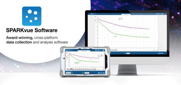
Winner: The Wireless Weather Sensor and SPARKvue software
With more than nineteen different measurements, including GPS, the Wireless Weather Sensor supports real-world environmental investigations that relate phenomena to data collection and analysis within SPARKvue. Together, the Wireless Weather Sensor and weather features within SPARKvue create a coherent solution for performing both long-term and short-term environmental inquiry at any science level. The Weather Dashboard within SPARKvue intuitively displays live and logged data, while SPARKvue’s ArcView GIS mapping integration supports geospatial investigations and analysis.

This sensor would provide extra opportunities for data collection in environmental science. It does offer a variety of options for experimental situations-19 in all. Experiments can be of short duration or long term. The weather vane is mentioned as an extra device to enhance data collection.

— Science Educators’ Best of Show Judge


Who Discovered Spectroscopy?

Similar to many scientific concepts, spectroscopy developed as a result of the cumulative work of many scientists over many decades. Generally, Sir Isaac Newton is credited with the discovery of spectroscopy, but his work wouldn’t have been possible without the discoveries made by others before him. Newton’s optics experiments, which were conducted from 1666 to 1672, were built on foundations created by Athanasius Kircher (1646), Jan Marek Marci (1648), Robert Boyle (1664), and Francesco Maria Grimaldi (1665). In his theoretical explanation, “Optics,” Newton described prism experiments that split white light into colored components, which he named the “spectrum.” Newton’s prism experiments were pivotal in the discovery of spectroscopy, but the first spectrometer wasn’t created until 1802 when William Hyde Wollaston improved upon Newton’s model.

William Hyde Wollaston’s spectrometer included a lens that focused the Sun’s spectrum on a screen. He quickly noticed that the spectrum was missing sections of color. Even more troublesome, the gaps were inconsistent. Wollaston claimed these lines to be natural boundaries between the colors, but this hypothesis was later corrected by Joseph von Fraunhofer in 1815.

Joseph von Fraunhofer’s experiments replaced Newton’s prism with a diffraction grating to serve as the source of wavelength dispersion. Based on the theories of light interference developed by François Arago, Augustin-Jean Fresnel, and Thomas Young, Fraunhofer’s experiments featured an improved spectral resolution and demonstrated the effect of light passing through a single rectangular slit, two slits, and multiple, closely spaced slits. Fraunhofer’s experiments allowed him to quantify the dispersed wavelengths created by his diffraction grating. Today, the dark bands Fraunhofer observed and their specific wavelengths are still referred to as Fraunhofer lines.

Throughout the mid 1800’s, scientists began to make important connections between emission spectra and absorption and emission lines. Among these scientists were Swedish physicist Anders Jonas Ångström, George Stokes, David Atler, and William Thomson (Kelvin). In the 1860’s, Bunsen and Kirchhoff discovered that Fraunhofer lines correspond to emission spectral lines observed in laboratory light sources. Using systematic observations and detailed spectral examinations, they became the first to establish links between chemical elements and their unique spectral patterns.

It took many decades and more than a dozen scientists for spectroscopy to be well understood, and most modern models weren’t developed until the 1900’s. Today, there are physicists, biologists, and chemists using spectroscopy in their day-to-day lives. For more information, visit our in-depth guide, What is Spectroscopy? or check out our other blog post, “What is the Difference Between Spectroscopy and Microscopy?”

2020 Skills Sheridan Competition

Sheridan College (Davis Campus) conducted their 3rd annual Skills Competition on March 4th, 2020, a day dedicated to recognize and celebrate the accomplishments of the students from various programs within the Faculty of Applied Science and Technology. Previously, professors selected their top students to compete in the Skills Ontario competition but with Sheridan’s new Skills Trade Centre, a more engaging way to select the students was brought forward.

Participants choose one stream and put their skill and knowledge to the test while engaging in a friendly competition with their peers. Some of the various streams included electrical engineering, information technology, precision machining, computer engineering, media management, web design, and welding.


AYVA was proud to be a sponsor for this years’ event. It was an honour to be able to witness the extraordinary projects presented by the students.

At the end the competitions, students and sponsors were gathered together for the presentation of the awards.

First, second and third place medals (which are made by the skills trade facility!) are awarded to the students.

Congratulations to all the winners and participants in this year’s competition!

Refrigeration Trainers to Suit Every Budget and Lab Size

AYVA offers teaching equipment for refrigeration covering the fundamental theories associated with thermodynamics, fluid mechanics and heat transfer – enabling students to understand HVAC environmental control in the real industrial and consumer world!

Environmental Control Teaching Equipment
The air conditioning and refrigeration (HVAC and R) industry designs, builds, maintains and repairs essential indoor comfort and cooling systems including heating, ventilation and air conditioning. The expanding markets for refrigeration and air conditioning and changing technology,  has created a growing need for training.

Our partner in England, TecQuipment (TQ) offers refrigeration training solutions and experiments that allow students to comprehend the workings of cooling towers, refrigeration and air conditioning; utilizing psychrometric and P-h charts.

TecQuipment Air Conditioning Trainer – EC-1501

The unit features an air-cooled condenser unit connected to an evaporator located in an air duct. The air duct contains relative humidity and temperature sensors on both sides of the evaporator. A small fan provides air flow down the duct and can be manually adjusted.

The refrigeration circuit features high and low pressure gauges, a pressure switch, sight glass, filter dryer and TEV valve. The circuit also includes pressure transducers that connect to the instrumentation.

Four thermocouples placed around the refrigeration circuit allow observation of temperatures, these can be used for the calculation of potential super heating and sub-cooling.

Our partner in France, ERIDÈS offers a unique solution with transparent walls which lets student watch the visible condensation and evaporation allowing for the understanding of the cycle processes.

ERIDÈS Refrigeration Cycle Demonstration Unit – MCFC10

This refrigeration cycle training unit allows for measurement of flow rate, pressure, temperature and more.

The fluid enthalpy chart is transposed onto a transparency at the centre of the unit allowing for rapid analysis of the fluid state parameters at any given point.

Transparent walls allow visibility on all sides while protecting both the equipment and its users. The visible condensation and evaporation allows for the understanding of the cycle processes. Once the machine has reached steady state, measurements can be taken and can be used even after the machine has been turned off.

Using the PASCO Smart Cart to Teach the Right-Hand Rule

We high school physics teachers tend to associate the right-hand rules with electromagnetism. As a student, my first encounter with a right-hand rule was when I was introduced to the magnetic field produced by the electric current in a long, straight wire: if you point the thumb of your right hand in the direction of the conventional current and imagine grasping the wire with your hand, your fingers wrap around the wire in a way that is analogous to the magnetic field that circulates around the wire.

I only later discovered that this same rule can be applied to rotational quantities such as angular velocity and angular momentum. The topic of rotation has become more important in AP physics when the program was updated from the older Physics B program. Strictly speaking, AP Physics 1 does not include the use of the right hand rule for rotation, but I have found that introducing it actually helps solidify student understanding of angular vectors.

Describing the direction of rotation as being clockwise or counterclockwise is helpful only if all parties involved have a common point of view, which is ideally along the axis of rotation. As with left and right, clockwise and counterclockwise depend on your point of view. This is why it is often preferable to describe translational motion in terms of north, south, east, west, up, and down, or with respect to a defined x-y-z coordinate system; directions can be communicated unambiguously, provided that everybody uses the same coordinate system.

It is precisely for this reason that the right hand rule can (and should) be used for rotational motion. Consider the hands of an analog clock. Assuming that the clock is a typical one, it will have hands that turn “clockwise” when viewed from the “usual” point of view, but if the clock had a transparent back and you were to view it from the back you would see the hands turning “counterclockwise!” The observed direction of rotation (clockwise or counterclockwise) depends on the observer’s point of view.

Instead of using clockwise and counterclockwise, we can describe the direction of rotation with a right hand rule: if you curl the fingers of your right hand around with the direction of the rotational motion, your thumb will point in the direction of rotation, which will be along the axis of rotation. Applying this to the above we find that when viewing a clock from the front, the rotation of the hands is three dimensionally into the clock (away from the observer), and when viewing a clock from the back side, the rotation of the hands is three dimensionally out of the clock (toward the observer). If two people view a transparent clock at the same time but one observes it from the front while the other observes it from the back (i.e. the clock is between the two people who are facing each other), they will disagree on which way the hands turn (clockwise or counterclockwise) but will agree on this direction if both use the right hand rule convention to describe the direction of the rotational motion – both observers will agree that it is directed toward the person viewing the back side of the clock.

When first learning about the right hand rule, students are often initially confused, with many students failing to grasp why such a rule is even useful in the first place. Before introducing the right hand rule I like to begin by holding an object such as a meter stick while standing at the front of the classroom. I then rotate the meter stick through its center so that the students claim that it is rotating “clockwise” when asked. Being careful to keep the rotational motion as constant as possible, I then walk to the back of the room. It’s important that the students see that at no point did I stop the rotation of the meter stick – it is still turning the same way as before, and yet at some point each student finds that they must turn around in order to continue to see it. Many students are astonished to see that the meter stick is now rotating counter clockwise from their (now reversed) point of view. This helps establish the need for a better way to describe rotation.

I then introduce the right hand rule and go through a couple of examples. Traditionally, this would have been the end of it, but last year I was able to take advantage of my newly acquired PASCO Smart Cart, which has a wireless 3-axis gyroscope (i.e. rotational sensor). The coordinate system is fixed with respect to the cart, and is printed on the cart itself, but I like to make this more visible by attaching cardboard cutout vectors onto the cart which make the axes more visible to the students while I hold the cart up for them to see. I then set up a projected display of the angular velocity of the cart along each axis simultaneously. I then ask the students how I must turn the cart in order to get a desired rotation of my choosing (i.e. ±x, ±y, and ±z).

I really like how the carts, along with the live display of the 3 angular velocity components make the admittedly abstract right hand rule so much more concrete. Seeing the display agree with our predictions makes it so much more real and is much, much better than me merely saying “trust me.” I have found that introducing and using this right hand rule with rotation has made using this same rule much more natural when using it to later relate the direction of current flow and the magnetic field.

Independent (Remote) Datalogging

In logging mode, wireless sensors collect data to their onboard memory for hours, days, weeks or even months at a time without needing to be connected to a computer, tablet, Chromebook or smartphone.

When the experiment concludes, simply connect the sensor to a device running PASCO software and download all the measurements it recorded.

How much does a windshield screen affect the temperature inside a car on a hot day? Using Wireless Temperature Sensors in logging mode makes it easy to find out.


Set up remote logging

Collect data directly on a Wireless Sensor instead of a computer or mobile device.

Note: Remote Logging is only available for PASCO Wireless Sensors.

  1. Open SPARKvue or click then select Start New Experiment.
  2. Click Remote Logging:
  3. Turn on the sensor then click the sensor which matches the device ID.

  4. Configure remote logging for each sensor:
      1. Select a sensor to configure from the Sensor menu.
      2. Toggle Sensor Enabled to Off if you don’t want to log data with this sensor.
      3. Set the Sample Rate using the left and right arrows. Toggle Common Sample Rate to Off to set different sample rates for each sensor.

    Tip: The configuration window indicates the amount of time that the sensor can log data below the sample rate. To increase the logging time:

      • Decrease the sample rate.
      • Disable unused sensors.
  5. Optional: Toggle Sensor Button Deferred Logging to On to start data logging by pressing the power button on the sensor.
  6. Click OK.

Data logging begins immediately after you click OK or press the power button on the sensor (if you selected Sensor Button Deferred Logging). The Bluetooth status light blinks yellow and green until data logging begins. When the sensor starts logging data, the Bluetooth status light blinks yellow.

Click OK and close SPARKvue. To stop data logging, turn off the sensor or connect it to SPARKvue to download the data.

Download remotely logged data

Download data remotely logged on a Wireless Sensor for data analysis. You can download the data to multiple devices as long as data isn’t deleted from the sensor after downloading it.

  1. Open SPARKvue or click then select Start New Experiment.
  2. Click Remote Logging .
  3. Turn on the sensor or press the power button if the sensor is currently logging.
    Note: The sensor doesn’t appear in Wireless Devices when the Bluetooth status light blinks yellow. Press the power button to make the sensor appear.
    Tip: Connect the sensor using USB, if available, to download data at a faster rate.
  4. Select the sensor under Sensors with data.
  5. In the Logged Data window, select Download Data.
  6. Select a method to download the data:
    • Templates
      Use this method to download the data into a new file.

      1. In the Select Measurements for Templates panel, select up to three measurements to display.
      2. In the Templates panel, select a template or a Quick Start Experiment to display the selected measurements.
    • Quick Start Experiments
      Use this method to download the data to a new Quick Start Experiment file. Names of Quick Start Experiments appear if available for the connected sensor.

      Select a Quick Start Experiment from the list, if available.

    • Add to existing experiment
      Use this method to download the data to an existing experiment file.

      1. Click Open PASCO Experiment or Open Saved Experiment.
      2. Select a file to open.


SHARE YOUR CART